Shop by Department

SKU:
Categories:Novastar
 Advanced design for reliability and stability
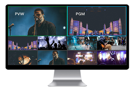
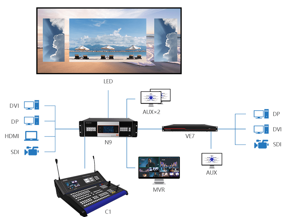
When the N9 is used with VE7, the input source can be increased to 16 channels, up to 5 channels 4K inputs, and the AUX output is increased to 3 channels, which is enough to meet the needs of various complex application
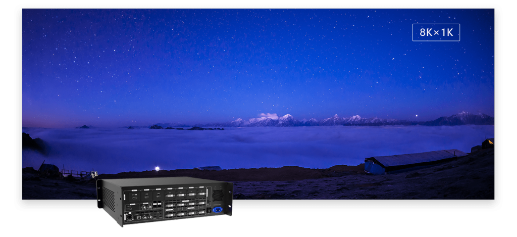
Each group includes a main connector and a backup connector. A maximum of 4 connectors can be used for mosaic output. The mosaic layout can be 4×1, 1×4 or 2×2. The maximum loading capacity can reach 8,800,000 pixels and the maximum mosaic width can be up to 8192 pixels.
Supports 4 single-link connectors or 2 dual-link connectors for mosaic output.
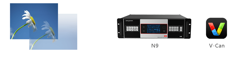
You can load an image file from the control computer or C1 event controller, or you can also capture an input source image displayed on the screen as the BKG image.
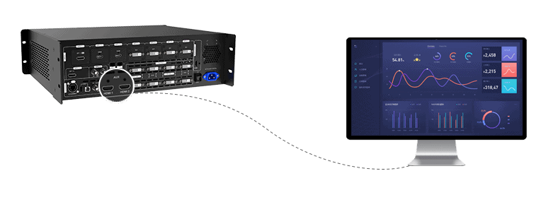
Supports input resolution management for DVI, HDMI and DP connectors.
A total of 32 user presets can be created and saved as templates which can be used directly and conveniently.
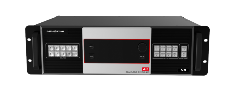
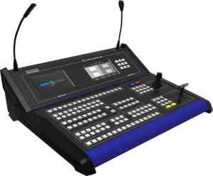
You can operate the N9 via its front panel, the V-Can smart control software or C1 event controller.
Input | |
| INPUT-1 | DP 1.1 connector Supports 3840×2160@30Hz video source input (downward compatible) and custom resolutions. |
| INPUT-2 | HDMI 1.3 connectors Support 1920×1080@60Hz video source input, any input resolution that conforms to VESA standard and custom resolutions. |
| INPUT-3 | |
| INPUT-4 | DVI connectors Supports 1920×1080@60Hz video source input (downward compatible), any input resolution that conforms to VESA standard and custom resolutions. |
| INPUT-5 | |
| INPUT-6 | |
| INPUT-7 | |
| INPUT-8 | DP 1.2 connector Supports 3840×2160@30Hz video source input (downward compatible) and custom resolutions. |
| INPUT-9 | 3G-SDI connector Supports 1920×1080@60Hz video source input (downward compatible). Supports de-interlacing processing. |
| SDI LOOP for SDI signal loop output | |
Output | |
| HDMI | HDMI output connector, capable of monitoring 9 input sources, PVW and PGM |
| DVI1-DL/PGM1 | DVI 1 output If the output mode is set to dual link, this connector is DuallinkOut1. |
| DVI2/PGM2 | DVI 2 output If the output mode is set to dual link, this connector is invalid. |
| DVI3-DL/PVW1 | DVI 3 output If the output mode is set to dual link, this connector is DuallinkOut2. |
| DVI4/PVW2 | DVI 4 output If the output mode is set to dual link, this connector is invalid. |
| HDMI1/HDMI2 | 2 Aux output connectors |
Control | |
| ETHERNET (RJ45) | A control connector |
| USB (Type-B) | For the connection with control computer |
| USB (Type-A) | For cascading N9 units |
IN–Genlock– LOOP | For synchronizing cascaded devices |
| OPT OUTPUT | 4 optical fiber connectors for controlling the VE7 video input expander |
Power | |
| AC100V-240V~ 50/60Hz | AC power connector |